
title: “Building A Magnetic Loop Antenna” date: 2021-05-15 00:00:00 categories: [amateur radio] tags: [ham radio, antenna, homebrew, radio] — During the 2020 COVID-19 pandemic I decided to dive back into the world of amatuer radio, building a workbench/ham radio “shack”, and building a few antennas to get on the air. I live in a fairly urban area of Mountain View, CA with limited antenna options at my apartment. Horizontal wire antennas perform poorly low to the ground and it’d be difficult to erect a vertical antenna without getting my landlords permission which landed me at “Magnetic Loop” antennas. I’ve always wanted to build one! It was time to grab some tools and start cutting copper pipes.
This antenna tunes between the 10m (10MHz) through 15m (21MHz) ham bands and can handle up to 20W of power. I used a stepper motor and gearing to allow remote tuning via a Raspberry Pi.
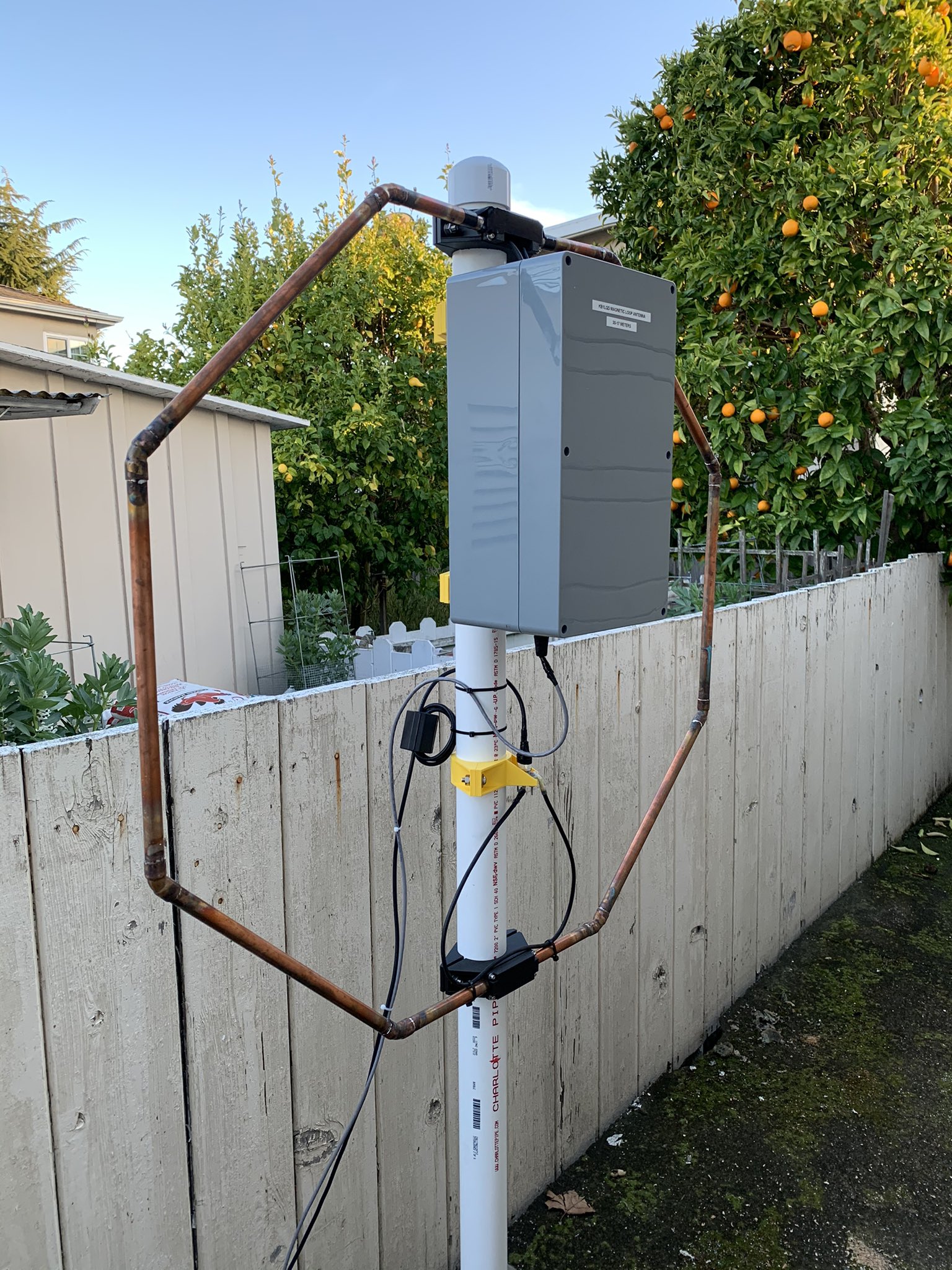
The antenna works! Here’s a preview of my first receiving test after the initial build.
This is not a detailed how-to article but I will provide helpful links and insight I discovered during this design/build.
You can find my GitHub repository for this project here.
References
There are many resources online about magnetic loop, A.K.A Small Transmitting Loop (STL) antennas. Additionally, there is a lot of misinformation including some in very popular resources listed below. Ultimately a mix-and-match will fill in most details and key tradeoffs. It’s an antenna and there’s no black-magic RF noise filtering involved.
- www.66pacific.com Small Transmitting Loop Calculator
- Non-Stop Systems Magnetic Loop
- W8JI Magnetic Loop Analysis
- This is a great in-depth technical resource & it’s classic ham-radio web 1.0 HTML!
Antenna Design
I set off to design this antenna by hand using online resources and the ARRL Antenna Handbook but life had other plans. Wanting use this project to learn FreeCAD designing the brackets and to get on the air I opted to just use the great www.66pacific.com STL antenna calculator.
This online calculator is self-explanatory and informative, I got the information needed to support the frequencies I wanted and purchase a suitable capacitor that can handle the high voltage expected. STL’s are a more exotic antenna from the common dipole antenna creating 1000’s of volts and many Amps of current with just 20 Watts of RF power. This exotic functionality is due to the very very low radiation resistance of this antenna.
3D Printed Bracket Design
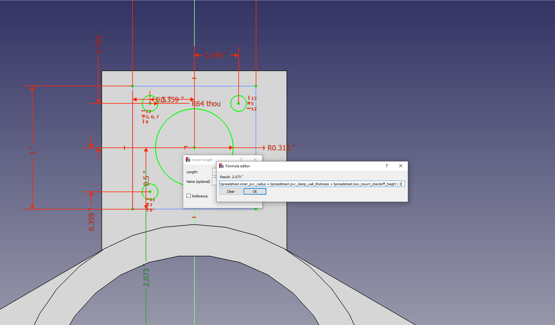
I used this project to learn the basics of FreeCAD mechanical CAD software. 3D printing made attaching the copper piping, coupling loop, and capacitor tuning enclosure easy! I had not used mechanical CAD tools prior so after a bit of riding the struggle bus, working through tutorials, I wrapped my head around parametrically creating components. My design files improve incrementally with the latter (coupling loop bracket) employing FreeCAD spreadsheet relationship dimensions allowing easy changes to the features and dimensions of the part.
The overall structure of the loop is just an octagon created using copper pipes and 45 degree elbows.
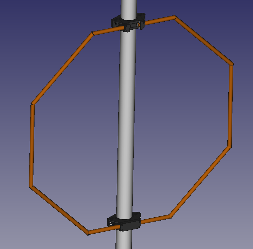
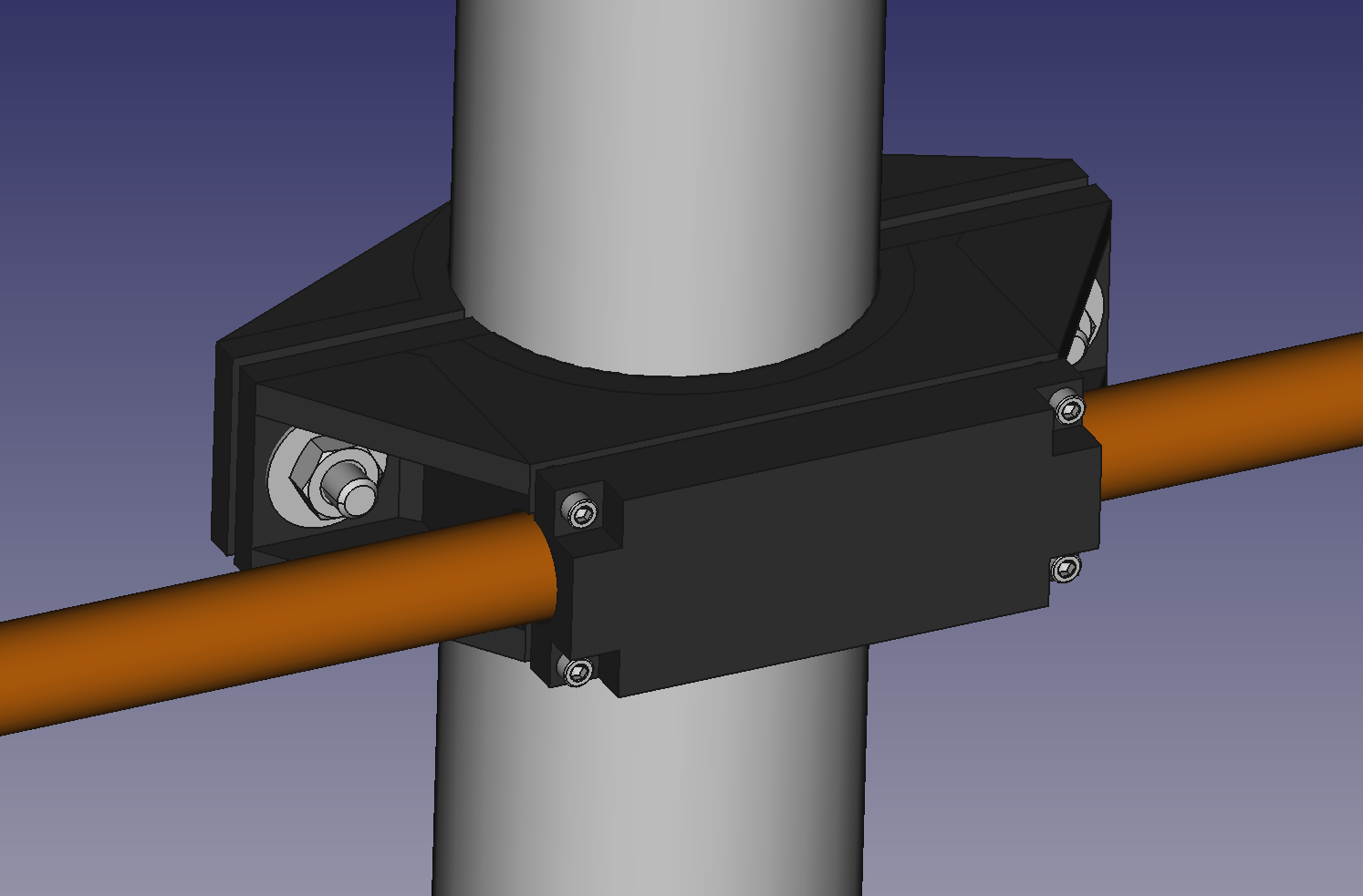
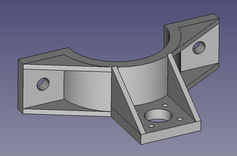
This is a fairly simple clamp I made to hold the loop to the PVC mast but still allow easy removal of just the loop itself.
The coupling loop part is the most well designed part as it was my last part in FreeCAD. Here is the SO-239 RF connector mount where the coupling loop is placed. The radio coax attaches from my radio to this connector.
Tuning Capacitor Housing
I decided there wasn’t a strong need to model the capacitor, stepper, and mounting brackets/gearing in FreeCAD and opted to just use paper designs in my notebook. I used this opportunity to practice my hacksaw, filing, and drilling skills.
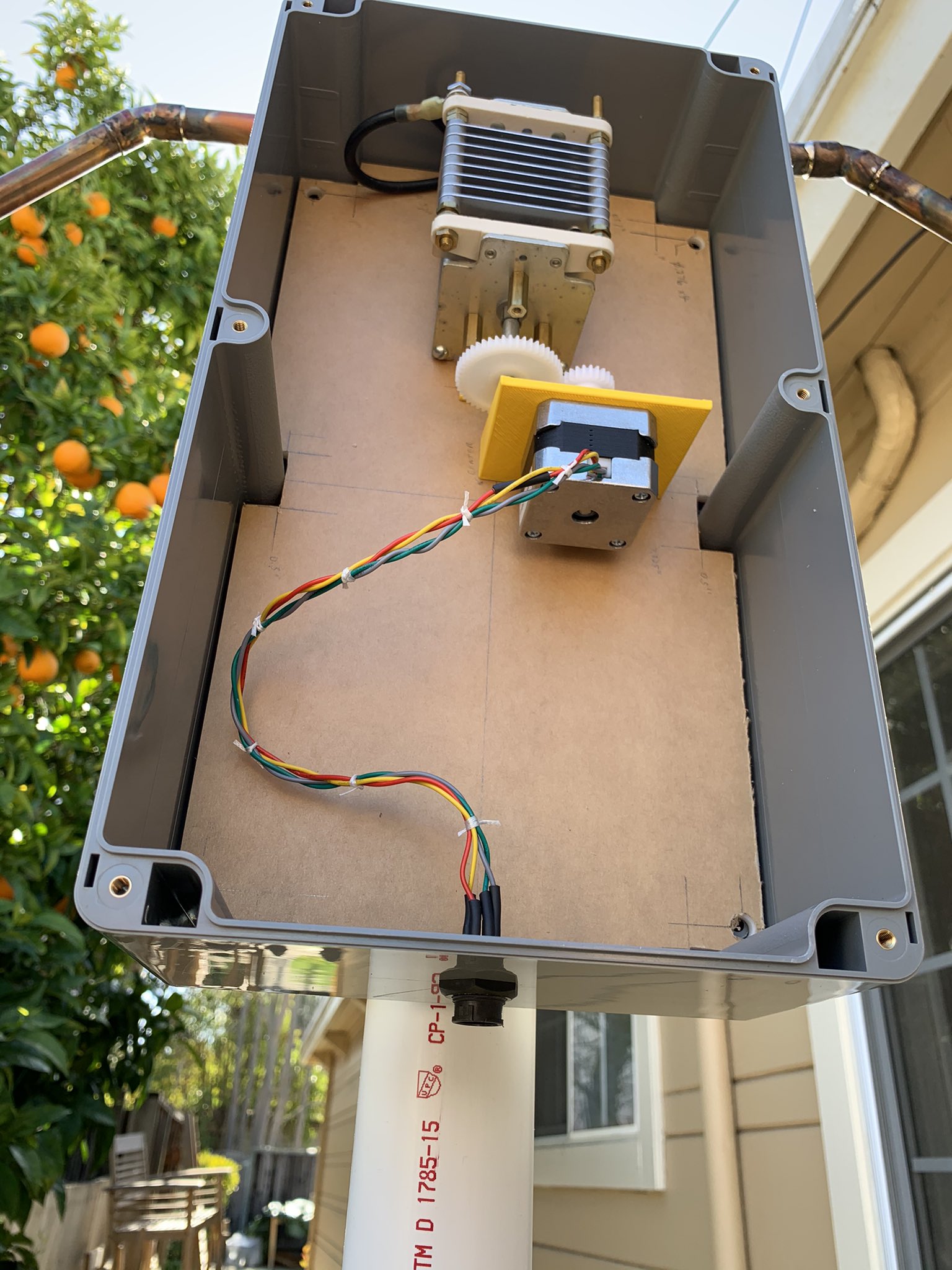
A single piece of acrylic sheet was used as a baseplate, it was cut into shape the fit a Polycase WA-44 Enclosure. I used a simple gearing ration of 1:2 between the stepper motor and capacitor, this works reasonably well although it’s easy to overshoot the tuning and a lower gearing ratio would make this easier.
Note, a redesign of the stepper bracket was made to increase rigidity.
Does It Work?
It does! I can tune the loop capacitance and thus frequency using a simple python script. Tuning is still manual but quite simple, turn clockwise or counterclockwise until the noise floor increases dramatically. Using a few quick tuning transmissions I can fine-tune to about a 1:1 SWR. Here’s a video using the loop antenna during a contest, note that I took this video originally to capture a quick HF upconverter I designed with some spare parts and an NE602 mixer I had.
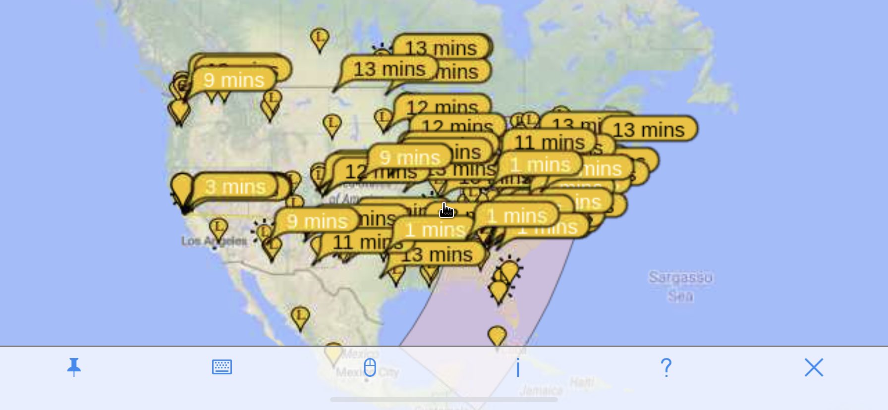
The www.pskreporter.com report below shows that my FT8 signals are reaching across the United States and I’m receiving folks similarly!
Key Components
- 1/2” copper water pipe
- 15-120pf 2.8KV air variable butterfly capacitor (RFParts 73-175-17)
- 2 1/2” Schedule 40 PVC (Mast)
- 3D Printed PVC mounting brackets (designed using FreeCAD)
- Polycase WA-44 enclosure
- Raspberry Pi 3
- Adafruit DC and Stepper Motor HAT